Somewhere around ninth-grade physics, most people in English-speaking countries get the same diagram: a cross-section of a wing, air splitting at the leading edge, and a caption explaining that the upper surface is more curved, so air travels farther over the top, has to go faster to “keep up” with the air underneath, and — thanks to Bernoulli’s principle — that extra speed means lower pressure on top and higher pressure below. Net result: the wing gets sucked upward. It’s tidy, it fits in one textbook panel, and pilots have had it explained to them this way for decades.
Then at some point you run into the counter-argument that’s been circulating for years on aviation forums and YouTube: “That’s completely wrong. Real lift comes from Newton’s third law — the wing shoves air downward, and the reaction pushes the wing up. Pressure differences are a side effect at best. Actually, the whole plane is just muscled into the air by engine thrust, like a really expensive kite.” Now you’ve got two competing stories, both delivered with total confidence, and no obvious way to referee between them without opening an aerodynamics textbook.
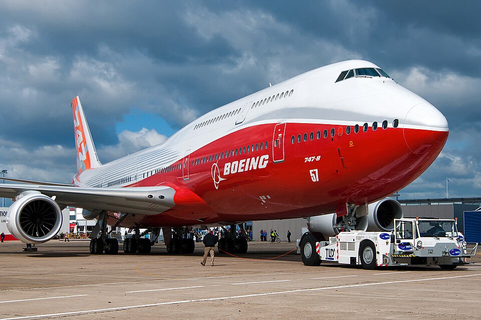

So which is it? Turns out neither position survives contact with the primary sources fully intact. Let’s check both against NASA’s own aeronautics references.
QUESTION
The textbook explanation usually runs like this: two air molecules that start out next to each other at the wing’s leading edge are assumed to reunite at the trailing edge — arriving “at the same time.” Since the upper surface is more curved, that path is longer, so the air moving over the top must travel faster to cover the extra distance in the same interval. Faster air means lower pressure per Bernoulli’s principle, so the top of the wing ends up low-pressure, the bottom high-pressure, and the pressure differential lifts the wing. This is widely known as the “equal transit time theory,” and it’s still printed in textbooks and even some pilot training materials.
Push on that explanation a little and it gets shaky. Is there any physical law requiring the two air parcels that split at the leading edge to reunite at the trailing edge? Air molecules made no such promise to each other. And in the last several years, an equally confident rebuttal has spread in the opposite direction: “Bernoulli is nonsense — real lift comes from Newton’s action-reaction law. The wing pushes air down, so the reaction pushes the wing up; pressure differences are secondary at best.” Some versions go further still, claiming an airplane essentially flies the way a kite does, hauled aloft by raw engine thrust.
So there are really two questions stacked on top of each other. First: exactly where, and why, does the equal transit time theory fail? Second: how much truth is there in the rebuttal — that Bernoulli is a myth and the “real” explanation is Newton plus thrust? The short answer is that both stories are half right. Let’s check each one against primary sources.
CHECK
Equal transit time fails at its founding assumption
NASA’s Glenn Research Center addresses this theory head-on in an aeronautics education page titled, bluntly, “Incorrect Theory of Lift.” Its core objection is almost anticlimactic: “Two molecules near each other at the leading edge will not end up next to each other at the trailing edge.” [1] The requirement that the two streams “must” reunite at the trailing edge was never derived from the equations of fluid dynamics in the first place — it’s an assumption that sounded plausible and got repeated until it calcified into common knowledge.
The more damning problem is that the theory’s own prediction doesn’t match measured airflow. NASA’s page states it plainly: “The actual velocity over the top of an airfoil is much faster than that predicted by the ‘Longer Path’ theory and particles moving over the top arrive at the trailing edge before particles moving under the airfoil.” [1] The air on top doesn’t arrive at the same moment as the air below — it gets there first. And because equal transit time underestimates how fast the top-surface air actually moves, it also underestimates lift: “The lift predicted by the ‘Equal Transit’ theory is much less than the observed lift, because the velocity is too low.” [1] The theory fails qualitatively (its “why” is wrong) and quantitatively (its numbers are wrong).
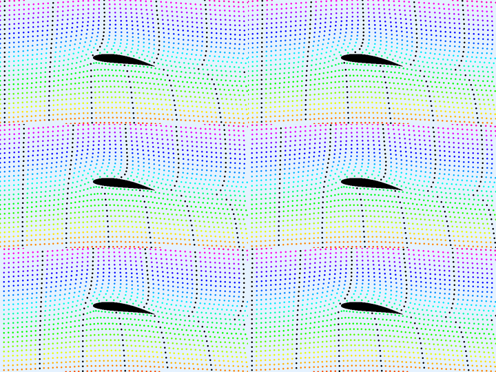

So why has an idea this broken survived in classrooms for so long? Aerospace engineer Graham Wild traced the error’s genealogy in a 2021 paper, and the trail goes back nearly 300 years. Jean le Rond d’Alembert first proposed the equal-transit assumption as a property of fluids in 1744; it was independently re-derived while applying Newton’s laws of motion to fluids in 1752; and Leonhard Euler reconfirmed it again in 1757. [2] In other words, equal transit time isn’t a modern misunderstanding — it’s an oversimplified 18th-century fluid model that outlived the physics that produced it.
But the pressure difference itself is real
Debunking equal transit time’s reasoning doesn’t debunk the underlying observation that a wing’s top and bottom surfaces sit at different pressures — that part is genuinely true. NASA’s “Aerodynamic Forces” page defines lift this way: “The component of the net force perpendicular to the flow direction is called the lift… the net force can be found by integrating (or summing) the pressure times the area around the entire surface.” [3] Integrate the local pressure over the entire wing surface, and the component perpendicular to the oncoming flow is lift; the component parallel to it is drag. Wind tunnel data and computational models both confirm the same standard picture: low pressure above the wing, high pressure below.
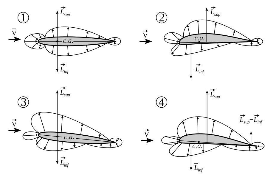

So “the top surface is low-pressure” is a real, measurable fact. The theory that goes wrong is the explanation for why — the claim that the two air streams must reunite at the trailing edge. The actual cause of the pressure difference is the circulation the wing imposes on the surrounding air, which we’ll get to below.
“Bernoulli is a myth” doesn’t hold up either — Bernoulli and Newton agree
That brings us to the newer, internet-native rebuttal: “Bernoulli is wrong, Newton is the real explanation.” This claim doesn’t hold up any better than the one it’s rebutting. NASA treats the Bernoulli (pressure) description and the Newton (momentum) description not as rival theories but as two different bookkeeping methods that arrive at the same number: “So both ‘Bernoulli’ and ‘Newton’ are correct. Integrating the effects of either the pressure or the velocity determines the aerodynamic force on an object.” [4]
Why do the two methods agree? A wing bends the surrounding airflow downward as it passes — this deflected flow is called downwash. Changing the air’s direction downward means changing its momentum downward, and by Newton’s third law, the reaction pushes the wing upward. That’s the Newtonian account. But in an idealized, frictionless flow, the relationship among pressure, velocity, and the curvature of the streamlines is governed by Euler’s equations — the fluid-dynamics equations that describe inviscid flow. A streamline curving downward (downwash) requires a pressure gradient across that region, and integrating that gradient over the wing’s surface produces exactly the pressure-difference lift that the Bernoulli account describes. “Pushing air down” and “creating a pressure difference across the wing” aren’t two competing phenomena — they’re the same flow field, described once in terms of momentum and once in terms of pressure. Framing it as Bernoulli versus Newton was never a coherent question to begin with.
“It’s just thrust, like a kite” is wrong too — the engine’s job is to beat drag
Another version of the internet pushback claims a plane basically gets muscled into the air by engine thrust, kite-style. This runs straight into NASA’s four-forces model of flight. An aircraft in the air experiences four forces — lift, drag, thrust, and weight — and in steady, level flight, lift balances weight while thrust balances drag. NASA states the engine’s actual job without ambiguity: “the job of the engine is just to overcome the drag of the airplane, not to lift the airplane. The wings are doing the lifting, not the engines.” [5] The math backs this up: on a wide-body airliner weighing around a million pounds, the combined thrust of all four engines typically tops out around 200,000 pounds-force — nowhere close to enough to hold that weight up on thrust alone. [5] And gliders, which carry no engine at all, fly perfectly well. [5] Lift is the wing’s job; thrust exists to push the aircraft forward through the air fast enough that the wing keeps generating lift, canceling out drag along the way — nothing more.
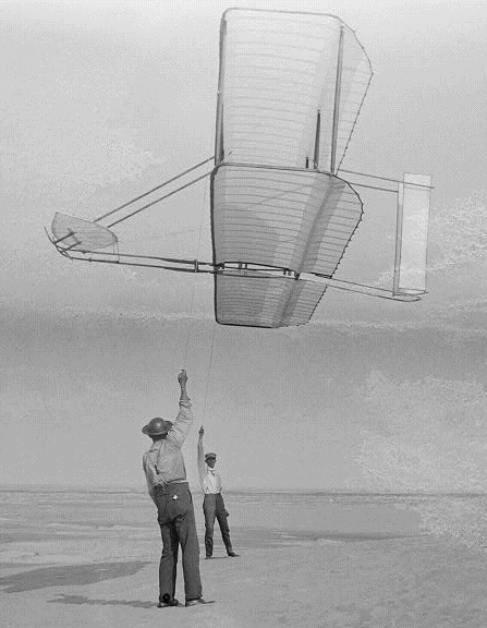

So how much lift, exactly — circulation and the Kutta–Joukowski theorem
Qualitative arguments — Bernoulli, Newton, doesn’t matter which — only get you so far. Neither answers the question an engineer actually needs answered: how many pounds (or newtons) of lift does a given wing produce? For that, aerodynamics has an established quantitative tool: circulation theory. Circulation (symbol Γ) is the integral of flow velocity around a closed loop enclosing the wing’s cross-section — a mathematical measure of how much rotational motion the wing imposes on the surrounding air.
That circulation value isn’t arbitrary. At a sharp trailing edge, physics demands that the flow leave smoothly — the upper and lower streams must merge and depart the trailing edge cleanly, without wrapping around it. This requirement is called the Kutta condition. As long as the fluid has even a small amount of viscosity (and real air always does), a flow that sharply whips around the trailing edge simply doesn’t happen. That single condition picks out one specific circulation value from an otherwise infinite mathematical family of possibilities. The relationship between that circulation and the resulting lift is the Kutta–Joukowski theorem, a standard result in fluid dynamics and aerospace engineering textbooks. [6] For a unit length of wingspan (one meter, say), lift per unit span is:
Here is air density, is the free-stream airspeed relative to the wing, and is the circulation defined above. What this equation tells you is that lift isn’t a vague “somehow it just floats” phenomenon — it’s a precise number produced by multiplying three physical quantities. Both the Bernoulli-style pressure integral and the Newton-style momentum integral, worked through fully, converge on this same circulation value Γ. The reconciliation between the two isn’t just diplomatic hand-waving — they meet inside the same mathematics.
Angle of attack and camber — even a flat plate can fly if you tilt it
One more useful wrinkle: you don’t need an elegantly curved wing to generate circulation and lift. NASA’s FoilSim reference states that “Lift is directly (linearly) proportional to angle of attack” over a limited range of angles. [7] A completely flat, uncambered plate — camber being the curvature of an airfoil’s cross-section — will generate lift once it’s tilted at an angle of attack (the angle between the wing and the oncoming airflow) relative to the airflow, following that same roughly linear relationship; only at exactly zero angle of attack does symmetry force lift to zero. [6] This is why a paper airplane, with a perfectly flat cross-section, can fly at all.
Cambered airfoils — asymmetrically curved top to bottom — behave differently: they can generate lift even at zero angle of attack. NASA notes that “with camber, an angle of attack can be determined for which the airfoil produces no lift” [8] — implying that this “zero-lift angle of attack” usually isn’t zero itself. Most real airliner wings use exactly this kind of camber, which is why a jet can be flying nearly level in cruise and still be generating lift continuously. What actually determines lift, in the end, isn’t “which surface is longer” — it’s the circulation produced jointly by angle of attack and camber.
FACT
Here’s where the physics actually lands. Equal transit time is wrong: the assumption that air splitting at the leading edge must reunite at the trailing edge isn’t physically required, and in reality, the air over the top arrives first. [1] But the popular rebuttal — “Bernoulli is a myth, it’s really Newton and thrust” — is equally inaccurate. The pressure difference across a wing is real, [3] and Bernoulli’s pressure account and Newton’s momentum account are two equally valid, complementary ways of integrating the same flow field, not competing theories. [4] Thrust’s job is to overcome drag and keep the aircraft moving forward — it’s a separate force from lift entirely [5] — and the actual magnitude of lift is a computable quantity, given by the Kutta–Joukowski relation . [6]
So this was never really a Bernoulli-versus-Newton fight to begin with. Both descriptions start from the same underlying equations (Euler’s equations for inviscid flow) — one measuring with a pressure gauge, the other with a momentum scale — and both were correct from the start. If anyone comes out looking bad here, it’s equal transit time theory: it happened to land on the right conclusions (“the top surface is faster,” “the top surface is lower pressure”) while getting the reasoning behind them completely wrong — like a test answer that’s correct but shows none of the actual work, and the work it does show is fabricated.
There’s one more misconception worth clearing up. You’ll sometimes hear that aircraft designers “don’t really understand” lift and just lean on computer simulations instead. That’s not a knowledge gap — it’s a purely mathematical one. The Navier–Stokes equations, which govern fluid motion in general, are nonlinear partial differential equations, and nobody has yet proven that smooth, well-behaved solutions always exist for arbitrary three-dimensional shapes. This is such a fundamental open problem that the Clay Mathematics Institute lists it among its seven Millennium Prize Problems, each carrying a $1 million reward. [9] That’s why NASA and the rest of the aerospace industry can’t simply hand-solve these equations for a real wing or fuselage shape — instead they approximate solutions using computational fluid dynamics (CFD) and verify them against wind tunnel data. NASA’s own FUN3D software, widely used across the U.S. aerospace industry and academia, is ultimately a tool for solving the Navier–Stokes equations numerically. [10] The physics of lift has been settled for a long time; what’s missing is a hand-calculable formula that applies the physics exactly to an arbitrary shape. It’s the same reason automakers rely on wind tunnels and CFD to measure a new car’s drag coefficient — not because the underlying physics is a mystery, but because there’s no equation you can solve by hand for a specific, complicated shape.
References
[1]: NASA Glenn Research Center, “Incorrect Theory of Lift,” https://www.grc.nasa.gov/www/k-12/VirtualAero/BottleRocket/airplane/wrong1.html (accessed July 2026)
[2]: Graham Wild, “On the Origins and Relevance of the Equal Transit Time Fallacy to Explain Lift,” arXiv:2110.00690, 2021, https://arxiv.org/abs/2110.00690
[3]: NASA Glenn Research Center, “Aerodynamic Forces,” https://www1.grc.nasa.gov/beginners-guide-to-aeronautics/aerodynamic-forces/ (accessed July 2026)
[4]: NASA Glenn Research Center, “Bernoulli and Newton,” https://www1.grc.nasa.gov/beginners-guide-to-aeronautics/bernoulli-and-newton/ (accessed July 2026)
[5]: NASA Glenn Research Center, “Four Forces on an Airplane,” https://www1.grc.nasa.gov/beginners-guide-to-aeronautics/four-forces-on-an-airplane/ (accessed July 2026)
[6]: John D. Anderson Jr., Fundamentals of Aerodynamics, 6th ed., McGraw-Hill Education, Ch. 3–4 (thin airfoil theory, circulation theory, the Kutta–Joukowski theorem, the Kutta condition, and the zero-lift angle of attack for symmetric airfoils) — a standard result established in fluid dynamics and aerospace engineering textbooks
[7]: NASA Glenn Research Center, “How Lift Changes” (FoilSim Manual), https://www.grc.nasa.gov/WWW/K-12/FoilSim/Manual/fsim0005.htm (accessed July 2026) — states “Lift is directly (linearly) proportional to angle of attack”; the exact zero-lift angle of attack for a symmetric flat plate (0°) is supported by [6] (thin airfoil theory)
[8]: NASA Glenn Research Center, “Aerodynamic Center,” https://www1.grc.nasa.gov/beginners-guide-to-aeronautics/aerodynamic-center/ (accessed July 2026)
[9]: Clay Mathematics Institute, “Navier–Stokes Equation,” Millennium Prize Problems, https://www.claymath.org/millennium/navier-stokes-equation/ (accessed July 2026)
[10]: NASA Langley Research Center, FUN3D Computational Fluid Dynamics Solver — numerically solves the Navier–Stokes equations and is widely used across NASA, U.S. aerospace industry, and academia, https://fun3d.larc.nasa.gov/